In today’s competitive manufacturing world, precision is the foundation of quality, efficiency, and customer trust. Whether you’re producing CNC turning parts, steel fittings, hydraulic components, or custom-machined pieces, achieving consistent accuracy relies on three essential pillars: technical print comprehension, inspection tool, and thread gauge inspection.
This guide breaks down these fundamental skills and best practices to help machinists, inspectors, and manufacturers strengthen their quality control process and deliver reliable, high-performance parts.
Understanding Technical Prints: The Blueprint of Manufacturing Success
Technical prints (2D drawings) act as the core communication tool between engineers, machinists, and quality teams. They outline every requirement needed to manufacture a part accurately—including dimensions, tolerances, materials, GD&T symbols, and surface finishes.
Key elements to focus on when reading technical prints:
1. Revision Level
Always verify you’re working with the latest revision. Outdated prints cause scrap, rework, and production delays.
2. Tolerances
Understanding tolerance ranges is crucial for quality control, especially when machining tight-tolerance cnc components .
3. Section Views & Reference Dimensions
These views reveal hidden geometry, internal features, or critical relationships that cannot be seen from standard projections.
4. Concentricity
Concentricity is a critical geometric tolerance used to evaluate the alignment of a part’s axes.
It is especially important for rotating components, mating shafts, threaded connections, and sealing structures.
Proper concentricity ensures smooth operation, reduces wear, and prevents assembly deviations.
5. Surface Roughness
Based on the technical drawing we need notice the suface roughness carefully , normally cnc lathe machining could achieves roughtness of around Ra 1.0 demand .
Once the demand is more than Ra1.0 , like Ra 0.8 .
Achieving finer finishes may require additional processes such as fine turning, grinding, polishing, or using sharper cutting tools.
6-Surface treatment
Every detail noted in the drawing is the key to acheive high precision cnc parts.
Especially the surface treatment in the drawing , it can improve cnc turning parts service life, enhance appearance and aesthetics, and increase corrosion resistance and durability.
Surface treatment plays a crucial role in the quality and longevity of CNC turning parts. Proper finishing not only enhances appearance but also ensures functional performance under demanding conditions. The main types of surface treatments include:
-
Polishing – creates a smooth surface that reduces friction, improves wear resistance, and enhances precision assembly.
-
Electroplating & Galvanizing – deposit protective metal layers such as zinc or nickel to prevent corrosion and extend the part’s service life.
-
Anodizing – commonly used for aluminum parts, this treatment increases surface hardness, improves corrosion resistance, and provides a uniform finish.
-
Chemical Nickel Plating & Electrophoresis – enhance durability and resistance to wear and chemical damage, providing a reliable coating for high-performance components.
-
Blackening & Heat Treatment – improve fatigue strength, hardness, and overall structural stability of steel parts.
After these treatments, CNC turning parts are often subjected to salt spray testing to simulate harsh environments. This test evaluates corrosion resistance, ensuring that the chosen surface finishing can withstand real-world conditions and deliver consistent performance over time. By carefully selecting and applying the right surface treatment, manufacturers can significantly improve part reliability and customer satisfaction.
7. Common Print Symbols
For cnc turning parts , mostly 2D drawing is enough to cnc process tube fitting ,hose fitting and different type brass fitting etc .
3D drawing is usually custom made for the complex components.
Essential symbols include:
-
Diameter: ⌀
-
Depth: ↧
-
Counterbore: ⌴
-
Countersink: ⌵
-
TYP. (typical)
- roughness: Ra
Strong print comprehension reduces errors, improves workflow communication, and ensures every part meets the designer’s intent.
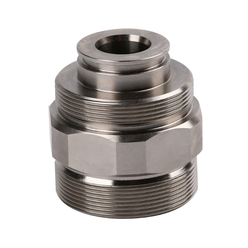
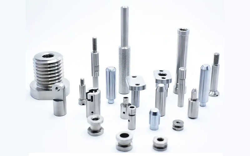
SHAF-ELBOW FITTING -HEX NUT-BULKHEAD FITTING -TUBE FITTING -HOSE FITTING CNC SERVICE
Inpsection tool :caliper,micrometer ,profile projector ,
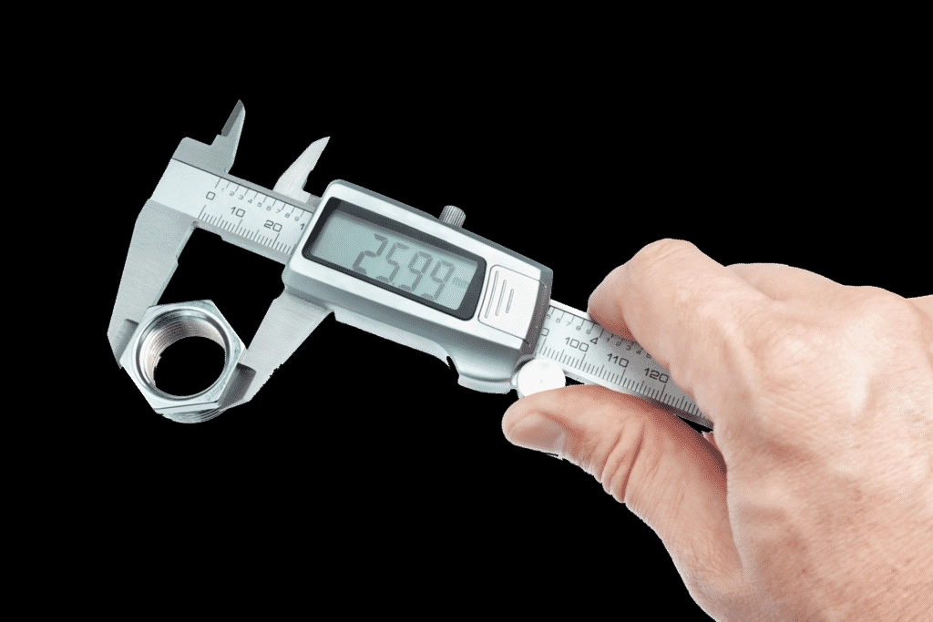
Calipers: Precision at Your Fingertips for Dimensional Accuracy
Calipers remain one of the most widely used measurement tools on the shop floor. From ODs and IDs to slot widths and recess depths, calipers allow machinists to quickly check dimensions throughout the machining process.
Best practices for using calipers accurately:
-
Clean both the part and the caliper jaws
Small particles can distort measurements. -
Ensure proper jaw alignment
Full, parallel contact ensures reliable readings. -
Apply consistent, light pressure
Too much force can damage the tool or distort thin-walled features. -
Verify the zero point before measuring
Incorrect zeroing results in systematic errors. - Acurrate :±0.02 mm
It can satisfy mostly precision parts for cnc lathe parts. But
Consistent calibration and proper storage keep calipers accurate and extend their service life.However, for medical, aerospace, and other high-precision components, more advanced measuring instruments are required, such as micrometers and coordinate measuring machines (CMMs).
Micrometers: Precision Measurement for CNC Metal Parts
For high-precision CNC metal parts, micrometers are essential tools to achieve accurate measurements. While calipers can provide quick checks with an accuracy of ±0.02 mm, micrometers deliver higher precision, often down to microns, making them ideal for medical, aerospace, and other high-precision components.
Best practices for using micrometers:
- Regular calibration ensures consistent accuracy.
- Keep surfaces clean to prevent measurement errors.
- Apply consistent, light pressure to avoid distorting delicate or thin-walled parts.
- Proper storage prolongs tool life and maintains reliability.
Using micrometers allows manufacturers to meet tight tolerances and guarantee the dimensional quality of CNC metal parts.
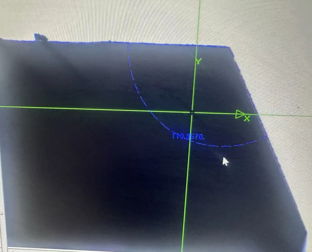
2. Profile Projectors: Detailed Inspection of Complex Geometries
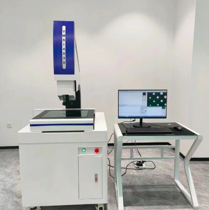
online cnc turning service
Profile projectors (also known as optical comparators) are indispensable for inspecting complex shapes, contours, and profiles in CNC metal parts. They provide a visual and precise measurement method that ensures every feature meets design specifications.the accurate can arrive 0.03UM.
Key advantages of profile projectors:
- Detect deviations in edges, radii, and intricate contours,groove etc. Dimensions that cannot be measured accurately with calipers or micrometers can be inspected using a profile projector (optical comparator).
- Ideal for quality control in high-precision industries like aerospace, medical devices, and automotive components.
A limitation of profile projectors is that they can only measure external contours and vertically projected planar dimensions. Internal features or hidden geometries of components require a coordinate measuring machine (CMM) for accurate inspection
By integrating profile projectors into the inspection process, manufacturers can guarantee quality and precision while maintaining compliance with industry standards.
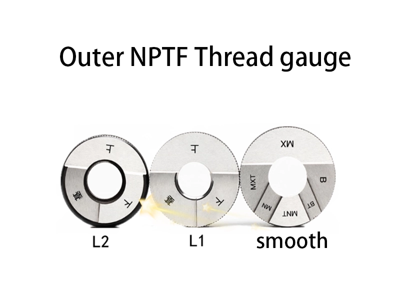
Thread Gauges: Ensuring Proper Fit, Seal, and Thread Accuracy
Thread gauges are vital for verifying whether threads are produced according to required standards like NPT, NPTF, BSPT, UNF, UNC, and metric threads. This is especially important for components used in fluid systems, hydraulic fittings, pneumatic lines, and precision pipe fittings.
Tips for effective thread gauge usage:
-
Inspect visually and by touch
Remove burrs, nicks, or deformation before gauging. -
Check for smooth, consistent engagement
Properly formed threads should mate without excessive friction. -
Verify concentricity and alignment
Misalignment leads to leaks, assembly issues, and performance failures.
Thread gauge inspections strengthen quality control and ensure reliable sealing performance—critical for NPT fittings, bulkhead fittings, valves, adapters, and industrial pipe components.
The Power of Integrating All Three: A Complete Quality Control System
Manufacturers who combine strong print-reading skills with proper caliper measurement and accurate thread inspection build a high-performance, quality-driven production workflow.
This integrated approach:
- Reduces scrap and rework
- Improves machining efficiency
- Ensures consistent part performance
- Builds long-term customer trust
- Supports compliance with industry standards
At Midland Industries, we promote these practical, proven methods to help machinists, suppliers, and manufacturers elevate their quality and deliver dependable precision components.
Final Takeaway
Precision is not just a requirement—it is a mindset.
Mastering technical prints, measurement tools, and thread inspection lays the groundwork for world-class manufacturing performance across industries such as machining, hydraulics, automotive, aerospace, plumbing, and custom fabrication.
By investing in these foundational skills, you strengthen your capability to consistently deliver accurate, reliable, and high-quality parts.