Introduction
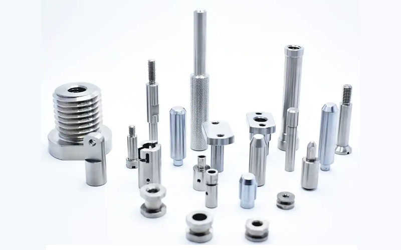
In precision manufacturing, CNC turning parts are widely used across industries, from automotive components and hydraulic fittings to industrial machinery and electronics. While CNC machines are highly capable, the quality of machined parts depends heavily on the clarity and accuracy of engineering drawings.
As a global CNC factory with hundreds of projects handled every month, we know that well-prepared engineering drawings are the foundation for producing high-quality, consistent components. This article explores how drawings affect CNC turning quality, common mistakes to avoid, and how professional factories review drawings before production.
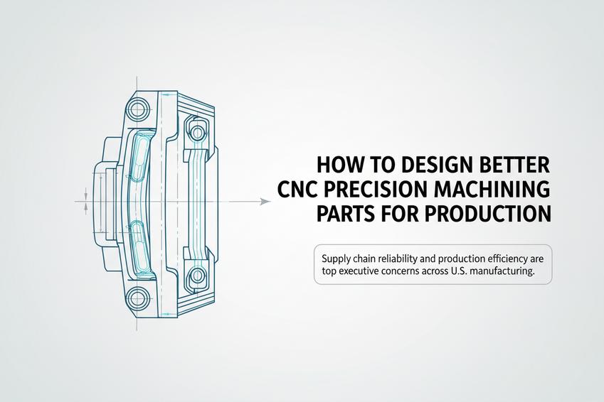
Why Clear Engineering Drawings Are Critical for CNC Turning
Engineering drawings serve as the blueprint for production, translating a designer’s vision into a physical part. In CNC turning, unclear drawings can lead to:
- Dimensional inaccuracies
- Surface defects requiring costly rework
- Misinterpreted thread standards or geometric specifications
Global manufacturers need clear, complete, and accurate drawings to plan tooling, machine parameters, and inspection processes. Proper drawings ensure parts meet exact specifications and function reliably in their applications.

Key Drawing Elements That Impact CNC Turning Quality
Several elements on engineering drawings directly influence CNC turning outcomes:
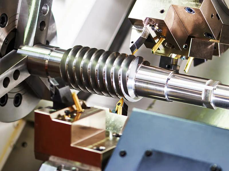
1. Dimensional Tolerances
Dimensional tolerances define the acceptable variation for each feature. They guide machinists on how precise each cut, bore, or thread must be.
- Tight tolerances (±0.01 mm) require high-precision CNC techniques, quality tools, and stable setups.
- Loose tolerances (±0.1 mm) allow faster production but may compromise functionality in high-precision applications like hydraulic fittings or automotive shafts.
2. Geometric Tolerances
Geometric tolerances control shape, orientation, and position, such as flatness, roundness, cylindricity, and perpendicularity.
- Improper geometric tolerances may lead to assembly misalignment or poor contact surfaces.
- CNC turned parts like shafts, bushings, and threaded fittings require strict geometric control to ensure proper functionality.
3. Surface Finish
Surface roughness affects both part aesthetics and functional performance, particularly for fluid flow or sliding contact.
- Rough surfaces may cause leaks in BSP/BSPT threads and reduce component lifespan.
- Precision CNC turning combined with sandblasting, polishing, and ultrasonic cleaning ensures surfaces meet specifications.
4. Thread Standards
Threaded features must comply with international standards, including BSPP (parallel), BSPT (tapered), ISO, or customer-specific requirements.
- Misunderstood thread specifications can cause assembly failure.
- Clear notation on drawings ensures compatibility with global fittings and equipment.
Critical Dimensions (KCC) and How to Identify Them
Not all dimensions are equal. Key Critical Characteristics (KCC) are dimensions that directly affect function, assembly, or safety.
Steps to identify KCCs:
- Review assembly requirements and how the part interacts with other components.
- Identify dimensions that affect sealing, fit, or movement.
- Clearly mark these dimensions on the drawing.
For instance, the inner diameter of a precision bearing or the thread pitch of a hydraulic fitting is often a KCC. At our factory, KCCs are prioritized in tool selection, machine setup, and inspection to ensure critical features remain within tolerance.
Common Engineering Drawing Mistakes That Cause Quality Issues
Even experienced engineers make errors. Frequent mistakes include:
- Missing tolerances or incomplete geometric specifications
- Ambiguous thread or surface finish notes
- Conflicting dimensions
- Unmarked critical features
- Non-standard symbols or outdated standards
These errors can lead to production delays, part rejection, or costly rework, especially in high-volume or high-precision CNC turning projects.
How CNC Manufacturers Review Drawings Before Production
Professional CNC turning factories follow a structured review process:
- Initial Assessment: Check all dimensions, tolerances, threads, and materials.
- Feasibility Analysis: Determine if the part can be produced within specified tolerances using available machines and tooling.
- Process Planning: Define CNC turning strategies, cutting tools, speeds, feeds, and setups.
- Critical Feature Verification: Ensure KCCs, thread standards, and surface finishes are achievable and measurable.
- Client Communication: Clarify ambiguities, suggest optimizations, and confirm standards before production.
Our factory’s 100+ CNC machines, precision measuring tools, laser marking, and ultrasonic cleaning systems allow us to handle complex global orders efficiently, reducing the risk of defects.
Table: Tolerance and Surface Finish Impact on CNC Turning Quality
| Feature / Material | Tight Tolerance | Loose Tolerance | CNC Turning Impact | Recommended Inspection Method |
|---|---|---|---|---|
| Shaft Diameter | ±0.01 mm | ±0.1 mm | Ensures fit in assemblies; loose tolerance may cause vibration | CMM, Micrometer |
| Thread (BSP/BSPT) | ±0.02 mm | ±0.1 mm | Maintains sealing and assembly reliability | Thread Gauge, Optical Projector |
| Surface Finish (Ra) | 0.2–0.4 μm | 1.6 μm | Smooth surfaces reduce friction; rough surfaces may leak | Surface Roughness Tester |
| Geometric Features | ±0.01 mm | ±0.1 mm | Misalignment affects assembly and function | CMM, Projection Measuring Machine |
Tips for Global Buyers: Ensuring High-Quality CNC Turning Parts
- Provide complete and clear engineering drawings with all tolerances and finishes specified.
- Highlight critical dimensions and threads, especially BSP, BSPP, or BSPT standards.
- Choose manufacturers with advanced CNC capabilities and inspection tools, including CMMs, projectors, and surface analyzers.
- Discuss post-processing requirements upfront, such as sandblasting, laser marking, or ultrasonic cleaning.
Following these steps ensures smoother production, faster lead times, and higher-quality parts.
FAQ (Frequently Asked Questions)
Q1: Why are engineering drawings so important for CNC turning?
A1: Drawings provide detailed specifications, tolerances, surface finishes, and thread standards. Clear drawings reduce errors, improve consistency, and save time and cost.
Q2: How do I identify critical dimensions (KCC) on a drawing?
A2: Critical dimensions affect function, assembly, or safety, such as bearing diameters, thread pitch, or sealing surfaces. Mark them clearly on the drawing.
Q3: What happens if a drawing has missing tolerances or ambiguous notes?
A3: It may cause production delays, incorrect parts, or costly rework. Professional CNC factories clarify ambiguities before production.
Q4: What post-processing methods improve CNC turned part quality?
A4: Techniques like sandblasting, laser marking, ultrasonic cleaning, and polishing enhance surface finish, remove burrs, and prepare parts for assembly.
Q5: Can a CNC factory handle global orders with strict tolerances?
A5: Yes. Professional CNC factories with 100+ machines, precision measurement tools, and advanced post-processing capabilities can reliably produce high-precision parts for global clients.
Conclusion: Clear Engineering Drawings Minimize CNC Turning Errors and Ensure Part Quality
High-quality CNC turning parts start with well-prepared engineering drawings. Global buyers should partner with factories that understand drawings, identify KCCs, and have advanced CNC and inspection capabilities.
At our precision CNC turning factory, we combine 100+ CNC machines, professional inspection tools, post-processing capabilities, and engineering expertise to deliver parts that meet the most demanding specifications worldwide.
By emphasizing drawing clarity, proper tolerances, and thread standards, manufacturers and buyers achieve consistent precision, minimize machining risks, and maintain high-quality standards in every part produced.
Related topic :
Stable CNC Turning Processes for Reliable High-Precision Parts
Cutting Tool Management for CNC Turning Quality
CNC Turned Parts: How Machining Parts Manufacturers Control Accuracy and Inspection