Quality control in CNC turning is far more than post-production inspection—it is the backbone of consistent, repeatable manufacturing. In industries like hydraulics, automotive, petroleum machinery, pneumatic connectors, and gas pipe fittings, even minor deviations in turned components can result in assembly failures, leakage, or reduced service life.
For B2B buyers in the UK, Europe, and globally, understanding how to control CNC turning quality ensures reliability, repeatability, and lower risk in high-volume production.
Understanding CNC Turning Quality Control
CNC turning quality control is a systematic process to ensure each part meets engineering requirements, including:
- Dimensional tolerances
- Geometric accuracy
- Surface finish
- Thread quality
- Functional performance
Modern CNC workshops employ process-driven quality control, integrating design review, material inspection, machine and tool management, in-process monitoring, and final verification into a closed-loop system. Quality is built into every step, not checked only at the end.
For international buyers, suppliers with strong QC systems guarantee batch-to-batch consistency, avoiding costly defects in production.
Why Quality Control Matters
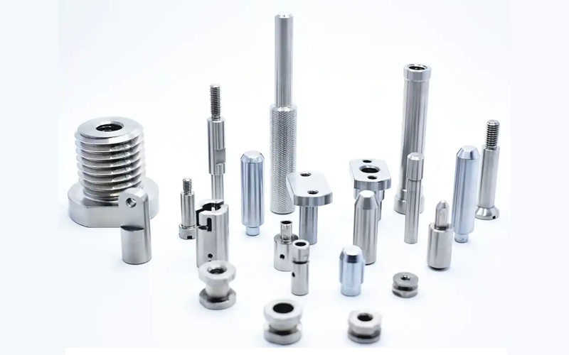
Precision CNC turned components are used in applications demanding tight tolerances and high repeatability:
- Hydraulic fittings and valves
- Automotive shafts, bushings
- Pneumatic and gas connectors
- Petroleum machinery components
Without proper QC, problems may include:
- Parts failing to fit during assembly
- Leakage due to poor surface finish or thread defects
- Premature wear from concentricity errors
- Inconsistent batch quality
- High scrap rates and delayed deliveries
Key takeaway: batch consistency is often more critical than individual part accuracy. One defective batch can disrupt supply chains, especially for high-volume industrial clients.
Common Quality Challenges
Even with advanced CNC lathes, challenges arise if the process is not fully controlled:
Dimensional Drift
| Material | Batch Size | Tool Life | Typical OD Drift | Typical ID Drift | Notes |
|---|---|---|---|---|---|
| Aluminum | 3000+ pcs | 3–4 days | +0.01mm | −0.01 mm | Stable, low drift |
| Copper | 3000+ pcs | 3–4 days | +0.01 mm | −0.01 mm | Stable |
| Stainless Steel | 3000+ pcs | ~1 hr | +0.07 mm | −0.07mm | Drift faster, monitor closely |
| Carbon Steel | 3000+ pcs | 0.5–1 day | +0.05 mm | −0.05 mm | Drift depends on tool condition |
Material choice affects drift, and tool condition and thermal variation are critical for maintaining dimensional stability.
Tool Wear and Breakage
| Material | Recommended Tool Life | Indicators for Replacement |
|---|---|---|
| Aluminum & Copper | 3–4 days | Surface marks, coarse chips |
| Stainless Steel | ~1 hour | Dimensional drift, chatter marks |
| Carbon Steel / Iron | 0.5–1 day | Surface finish deterioration, noise, stepped surfaces |
Operational tip: Track tool life by material and operation type; schedule replacements proactively to avoid batch drift.
Surface Finish Issues
- Rough surfaces or chatter marks often result from worn inserts or incorrect cutting parameters
- Material-specific strategies: adjust feed rates and spindle speeds per material for optimal finish
Thread Quality
| Surface Treatment | Typical Thickness | Effect on Thread |
|---|---|---|
| Standard plating | ±0.01 mm | Minimal |
| Electroplating / Electrowinning | 0.03–0.07 mm | Can loosen or tighten threads |
| Dacromet / Chrome | 0.03–0.07 mm | Requires prediction and monitoring |
- Most parts feature threads verified with Go/No-Go gauges
- Thread deburring with specialized tools eliminates burrs
- Risks include uneven plating or rolling during handling, potentially damaging threads
Batch Consistency
| Part Cycle Time | Batch Size | Inspection Interval | Notes |
|---|---|---|---|
| 2 minutes/part | 50 pcs | ~1.5 hours | Longer cycles, less frequent |
| 15 seconds/part | 50 pcs | ~13 minutes | Short cycles, more frequent |
| High-precision / fast cycles | Variable | Tighter intervals | Reduce risk of drift |
- Even if first parts are compliant, unmonitored processes lead to drift
- Multi-machine production: first article inspection required on all machines
- Track trends to prevent large-scale defects
CNC Quality Control Workflow
1. Drawing and Design Review
- Verify dimensions, tolerances, surface finish, and thread specifications
- Identify critical control dimensions
- Clear drawings prevent misinterpretation, reduce rework, and improve efficiency
2. Material Inspection and Traceability
- Materials: carbon steel, stainless steel, aluminum, copper (~10% of orders)
- Verify grade, dimensions, and surface condition
- Maintain batch traceability for regulated industries and long-term contracts
3. Machine, Tooling, and Process Management
- Machine condition, spindle runout, chuck concentricity, and fixturing influence precision
- Standardized roughing/finishing parameters ensure repeatability
- Follow tool replacement schedules by material (Al/Cu 3–4 days, Stainless ~1 hr, Iron 0.5–1 day)
4. First Article and In-Process Inspection
- FAI covers all dimensions, surface finish, and thread verification
- Inspect first part on each machine in multi-machine setups
- Sample critical dimensions during production based on cycle time
- Document trends to prevent large-scale defects
5. Post-Processing and Final Inspection
- Surface treatments (plating, anodizing, blackening) can alter dimensions
- Verify post-process dimensions and appearance
- Packaging inspection ensures protection against transport damage
Measurement Tools
- Projector, Coordinate Measuring Machine (CMM)
- Go/No-Go thread gauges
- Calipers, micrometers, depth gauges
Proper use ensures precision even in high-volume, multi-material batches.
Handling Surface Treatment and Thread Challenges
- Predict coating thickness carefully before processing
- Common problems: thin plating → loose threads; uneven plating → damaged threads
- Mitigation: thread finishing tools, pre-plating adjustments, in-process inspection
Customer Complaints and Preventive Measures
- Most common: surface damage during transport
- Solutions:
- Palletized packaging for metal parts
- Protective layers for small batches
- Small-batch logistics remain a challenge; careful handling is key
Selecting a CNC Supplier with Strong QC
Indicators of a reliable supplier:
- Structured FAI and in-process inspection
- Adequate measuring equipment
- Expertise in tolerance analysis, surface treatments, and multi-material machining
- Proven batch consistency in large orders
For buyers in the UK, Europe, and globally, these factors ensure predictable delivery and product performance.
Case Study: High-Precision Automotive Parts Production (Australian Client)
An Australian automotive parts manufacturer placed an order for 3,000 stainless steel components, each requiring ±0.02 mm tolerance with an internal bore depth of 60 mm and **chemical nickel surface treatment (0.02 mm thickness). The surface had to remain free from scratches to ensure proper assembly.
During initial production, we observed that internal bore machining generated significant iron chips, while maintaining high precision was critical. To address this, we implemented the following measures:
- Tooling and fixture optimization: Special long-hole tools were selected, and fixtures were adjusted to maintain bore concentricity and prevent deviations.
- Chip removal and cooling: High-pressure coolant and chip-scraping systems were used to minimize debris accumulation and protect the internal surfaces from damage.
- In-process monitoring and batch inspection: Every 10 parts were measured for critical dimensions and surface quality**, including internal bore depth, outer diameter, threads, and plating thickness.
- Surface treatment control: Chemical nickel coating was strictly maintained at 0.02 mm, ensuring uniform coverage and avoiding thread looseness or damage.
As a result, all 3,000 parts met the design tolerances**, threads passed Go/No-Go gauge verification, internal bores were clean and defect-free, and plating thickness was consistent. The client praised the stable precision, undamaged bores, and batch consistency**, confirming that the order fully met their automotive assembly requirements.
Conclusion: Building a High-Precision CNC Turning System
CNC turning quality is built into the process, not added afterward. From design review, material inspection, machine setup, tool management, first article inspection, process monitoring, to final verification, each step contributes to the final result.
Experience-based monitoring, precise tool management, and structured inspection protocols allow manufacturers to produce consistent, high-precision parts across large batches, minimizing risk and ensuring performance for demanding industrial applications.
Related topic:
Stable CNC Turning Processes for Reliable High-Precision Parts
Cutting Tool Management for CNC Turning Quality
CNC Turned Parts: How Machining Parts Manufacturers Control Accuracy and Inspection
How Engineering Drawings Affect CNC Turning Quality ?