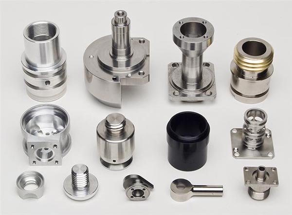
Precision Assembly Techniques for Dowel Pins in Metal CNC Components
Understanding Dowel Pin Selection Criteria
Dowel pin selection directly impacts assembly accuracy and mechanical stability. For metal CNC components, material compatibility is paramount—stainless steel dowels suit high-corrosion environments, while carbon steel variants offer cost-effective solutions for standard applications. The diameter tolerance must align with pre-machined hole specifications, typically maintained at ±0.005mm for precision assemblies. Length selection requires accounting for both component thickness and engagement depth, with standard practice ensuring 1-2mm protrusion above the mating surface to facilitate alignment verification.
Surface finish requirements vary by application: ground dowels with Ra 0.2-0.4μm surface roughness minimize friction in sliding assemblies, while turned components with Ra 0.8-1.6μm suffice for static positioning. Hardness considerations demand HRC 58-62 for load-bearing interfaces, whereas softer materials (HRC 45-50) may suffice for non-critical alignments.
Step-by-Step Assembly Protocol
Hole Preparation and Cleaning
Begin by verifying hole dimensions using calibrated bore gauges, ensuring diameter matches dowel specifications within ±0.01mm tolerance. Eliminate machining residues through ultrasonic cleaning with isopropyl alcohol, followed by compressed air purging at 0.6MPa to remove particulate contaminants. For threaded holes, employ tap cleaners to restore thread geometry before dowel insertion.
Lubrication Application Techniques
Apply molybdenum disulfide-based dry film lubricant to dowel surfaces using aerosol spraying, maintaining 300-500mm working distance to achieve uniform 2-3μm coating thickness. For liquid lubricants like synthetic grease, use micro-applicators to deposit 0.05-0.1ml precisely at the dowel entry point, preventing excess migration into mating surfaces. In high-temperature applications (above 150°C), opt for graphite-impregnated coatings that maintain lubricity without thermal degradation.
Insertion and Alignment Verification
Employ pneumatic arbor presses with force gauges calibrated to 50-100N range for controlled insertion, ensuring pressure application perpendicular to the mating surface within ±1° angular tolerance. For manual assemblies, use nylon-tipped hammers with 200-300g striking force, delivering 3-5 light taps in circular pattern to distribute stress evenly. Post-insertion, verify alignment using dial test indicators with 0.001mm resolution, measuring radial runout across three equidistant points on the dowel circumference.
Quality Control and Troubleshooting
Dimensional Inspection Protocols
Implement coordinate measuring machine (CMM) verification for critical assemblies, capturing 50-100 measurement points per dowel to generate 3D deviation maps. For batch production, use go/no-go gauges with ±0.003mm tolerance bands, conducting 100% inspection on initial production runs and 10% sampling thereafter. Visual inspection under 10x magnification must confirm absence of burrs, cracks, or coating defects on both dowels and mating holes.
Common Assembly Defects and Remedies
Mismatched dowel-hole diameters causing interference fits require reaming operations with carbide-tipped tools, maintaining 0.01-0.02mm oversize relative to nominal dowel diameter. In cases of insufficient engagement depth, machine counterbores to extend housing depth while preserving 1.5:1 length-to-diameter ratio for optimal load distribution. For misaligned components, employ laser alignment systems to identify angular deviations, then correct through selective material removal from mating surfaces using EDM wire cutting.
Long-Term Maintenance Strategies
Establish preventive maintenance schedules based on operational cycles, with dowel replacement intervals determined through wear rate calculations. For continuous-duty equipment, implement vibration analysis using accelerometers mounted on dowel-housing interfaces, triggering replacement when amplitude exceeds 5g RMS. In corrosive environments, apply protective coatings biannually using zinc-rich primers followed by epoxy topcoats, ensuring 150-200μm total dry film thickness.

