1. Introduction: The “One Millimeter” Mistake in CNC Machined Parts
In the world of precision manufacturing, a single decimal point is the difference between a high-performance component and a bucket of scrap metal. For global procurement teams, the biggest challenge isn’t just finding a factory—it’s ensuring that the CNC machined parts being produced exactly match the design intent, regardless of whether the designer used inches or millimeters.
We live in a dual-unit reality. While most of the world operates on the Metric (SI) system, many of the most advanced industries in the United States, such as aerospace, medical devices, and high-pressure hydraulics, still speak the language of Inches (Imperial).
At Yuhuan Hongqian Machinery Co., Ltd., located in the manufacturing hub of Taizhou, Zhejiang, we see thousands of blueprints every month. We’ve learned that “translation” isn’t just about math; it’s about understanding the culture of engineering. This guide will walk you through everything you need to know to ensure your next project is a success.+
2. What is the Core Difference Between Inch and Metric Standards?
Before we get into the heavy machinery, we need to understand why these two systems exist and how they affect the logic of a CNC machined part.
2.1 The Math Behind the Metal
The universal constant is: 1 inch = 25.4 millimeters.
While the math is simple, the philosophy is different. Metric systems are base-10, making them intuitive for scaling. Imperial systems are often based on fractions (1/2, 1/4, 1/8), which can lead to complex rounding issues when programmed into a CNC lathe that operates in a metric-native environment.
2.2 Tolerance “Shorthand”
One of the “human” elements of blueprint reading is implied tolerance.
-
On an Inch Drawing: A dimension written as
.500"usually implies a much tighter tolerance than0.5". The three decimal places signal to the machinist that this is a critical mating surface. -
On a Metric Drawing: Tolerances are almost always explicit. You will see
10.00 ± 0.02mmor a GD&T (Geometric Dimensioning and Tolerancing) symbol like a position or flatness requirement.
3. How to Navigate Thread Specifications: TPI vs. Pitch
If there is one area where CNC machined parts fail most often during assembly, it is the threads. You cannot simply “convert” a metric thread to an inch thread. They are fundamentally different geometries.
3.1 TPI (Threads Per Inch) Explained
In the Imperial system, we don’t measure the distance between threads; we count how many threads fit into one inch. This is known as TPI.
-
UNC (Unified National Coarse): Used for general applications where easy assembly is required.
-
UNF (Unified National Fine): Used when higher strength or finer adjustment is needed.
3.2 The “Points” (分) System: A Local Language
If you are working with suppliers in Asia, you might hear the term “Points” (分). This is an old but common industry shorthand for fractions of an inch:
| Imperial Fraction | Decimal Inch | Millimeter (mm) | Industry Nickname (China) |
| 1/8″ | 0.125″ | 3.175 mm | 1 Point |
| 1/4″ | 0.250″ | 6.350 mm | 2 Points |
| 3/8″ | 0.375″ | 9.525 mm | 3 Points |
| 1/2″ | 0.500″ | 12.700 mm | 4 Points |
| 3/4″ | 0.750″ | 19.050 mm | 6 Points |
| 1″ | 1.000″ | 25.400 mm | 8 Points |
4. Why Thread Accuracy Matters for Your CNC Machined Parts (H2)
Thread fit is not just about assembly; it is about load distribution, shear strength, and long-term vibration resistance. At Yuhuan Hongqian, we treat internal and external threads as two completely different engineering challenges.
4.1 Internal Threads: The “Drill Size” Mastery
When manufacturing internal threads (the “nut” side), the Drill Size is the most critical factor. The drill creates the Minor Diameter before the tap cuts the profile.
-
The 75% Rule: To ensure maximum strength without breaking tools, industrial standards require a thread depth of roughly 75%.
-
The Calculation: Our engineers use a precise formula to select the correct imperial drill:
$$mathbf{text{Drill Size} = text{Nominal Diameter} – left(frac{1}{text{TPI}}right)}$$Example: For a 3/8-16 UNC thread, the calculation is $0.375″ – 0.0625″ = 0.3125″$.
-
The Risk of Substitutes: Using a standard 8.0mm metric drill instead of the required 5/16″ (7.94mm) specialized drill creates a hole that is 0.06mm too large. This minor gap reduces the thread engagement area, significantly increasing the risk of “stripped threads” under high pressure.
4.2 External Threads: Controlling the Blank Diameter
For external threads (the “bolt” side), we don’t use drills. Instead, we start with a solid rod and use CNC turning tools to cut away material.
-
The “Subtraction” Logic: Here, the focus is on the Major Diameter of the blank.
-
Tolerance Classes (2A): An imperial Class 2A specification requires the blank diameter to be slightly undersized (by microns) to allow for plating or heat treatment. If the blank is left at the full nominal diameter (e.g., exactly 0.375″), the finished part will be too tight to fit into a standard 2B nut after coating.
-
Precision Turning: Our high-speed CNC lathes ensure that the “crest” and “root” of the thread are perfectly formed, preventing stress concentrations that lead to part failure in the field.
4.3 How Yuhuan Hongqian Guarantees a Zero-Defect Fit
We don’t rely on “feel.” Our quality control process is rigorous:
-
Dedicated Tooling: We maintain a massive inventory of dedicated Imperial Drills and Taps. We never substitute with “close-enough” metric sizes.
-
Metrological Validation: We use calibrated Go/No-Go Plug Gauges for internal threads and Thread Ring Gauges for external threads.
-
DFM Verification: During our initial design review, we verify that the requested thread class (e.g., 2A/2B or 3A/3B) matches the intended application, ensuring your CNC machined parts perform reliably from day one.
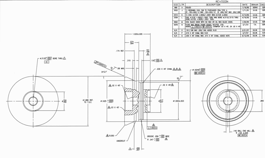
To understand the difference between a simple math conversion and real-world machining, let’s look at the specific dimensions on this imperial blueprint for a CNC machined part.
5.1 The “Four-Decimal” Precision Challenge
Look at the bore callout on the left: Ø.3125 (+.0003 / -.0001).
-
The Math: .3125″ is exactly 7.9375 mm.
-
The Machining Reality: The tolerance window here is only .0004″, which is approximately 10 Microns (0.010 mm). At Yuhuan Hongqian, we know that if a supplier treated this as a standard “8mm hole,” the part would be scrap. Achieving a 10-micron tolerance consistently across 3,000+ pieces requires the high-end thermal stability of our automated CNC lathes.
5.2 GD&T and Baseline Control
Notice the datum feature [-A-] and the circularity/positional symbols. On an imperial drawing, a callout of .0005 A means the feature must be within 12.7 microns of the baseline. We use Coordinate Measuring Machines (CMM) calibrated to microns to verify these inch-based dimensions. This ensures that when your CNC machined parts arrive, they assemble perfectly with your local US-sourced components.
5.3 Recognizing Specialized Tooling
The drawing also specifies a “1/4 BALL END MILL” and a specific “UNDERCUT.” These are not generic metric tools. A 6mm ball mill is NOT a 1/4″ (6.35mm) ball mill. Using the wrong tool changes the radius of the internal corners, which can lead to stress fractures in high-pressure applications. Our tool crib is fully stocked with both metric and imperial high-speed carbide tools to match your exact design requirements.
6. Common Mistakes to Avoid When Designing CNC Machined Parts
Based on 10+ years of experience, here is a checklist of errors that cause delays:
-
The “Zero” Error: In the US,
.500is common. In the Metric world, we write0.500. Forgetting the leading zero can lead to misinterpretation in automated OCR software. -
Rounding Discrepancies: If you convert
1/8"to3.17mminstead of the precise3.175mm, that 0.005mm difference can cause a press-fit bearing to fail. -
Missing Standard References: Always state if you are using ASME Y14.5 or ISO 1101. This tells the manufacturer how to interpret the GD&T symbols.
7. Yuhuan Hongqian: Your Partner for Precision CNC Machined Parts
Why do customers choose Yuhuan Hongqian for their most complex turning and milling projects? It’s because we bridge the gap between “drawing” and “reality.”
7.1 Advanced Factory Capabilities
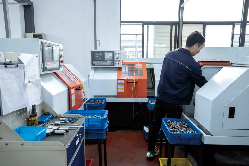
Our facility in Taizhou is built for high-volume, high-precision work:
-
Scale: 70+ high-precision CNC lathes.
-
Automation: 15 robotic gantry systems (truss robots) for 24/7 consistent production.
-
Capacity: 200,000 pieces per month.
-
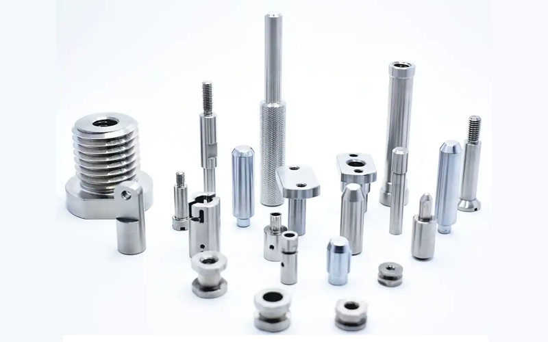
Materials: Expert machining of Stainless Steel, Brass, Aluminum, and Carbon Steel.
7.2 Our DFM Process (Design for Manufacturability)
We don’t just “hit start” on the machine. Every CNC machined part goes through our DFM review. Our engineers compare your 2D PDF with your 3D STEP file. If there is a discrepancy between the inch notation and the metric model, we stop and clarify. This proactive approach saves our clients thousands of dollars in potential errors.
8. FAQ: Frequently Asked Questions About CNC Machined parts
Q: Can I provide a blueprint in Inches and ask for the part in Metric?
A: Yes, but it is safer to provide a 3D CAD model. This ensures the CNC software reads the geometry directly, while the 2D drawing defines the tolerances.
Q: What is the standard MOQ for custom CNC machined parts?
A: At Yuhuan Hongqian, our standard MOQ is 3,000 pieces, which allows us to optimize our automated robotic cells for the best price-to-quality ratio.
Q: How do you ensure the precision of threads?
A: We use a combination of CMM (Coordinate Measuring Machines) and manual GO/NO-GO gauges. For high-precision orders, we provide full dimensional inspection reports.
9. Conclusion: Clarity is the Key to Precision
Whether you are designing a simple brass fitting or a complex aerospace housing, the clarity of your blueprint determines the quality of your CNC machined parts. By understanding the nuances of unit systems, thread callouts, and projection methods, you empower your manufacturer to deliver excellence.
Get a Professional Quote Today
Stop worrying about unit conversion errors. Partner with a factory that understands your language. Yuhuan Hongqian is ready to handle your high-volume OEM/ODM projects with the precision you demand.
Send Your Drawing – We’ll Identify Risks Before Production