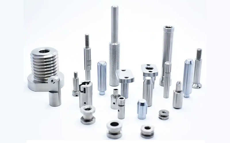
Introduction
In CNC machining, product accuracy is often associated with machine capability and cnc process control, but precision does not depend on machining alone. Even when cnc parts are produced on the same equipment using identical programs, different inspection methods can lead to noticeably different measurement results. This is a common source of confusion in quality control, especially when cnc parts appear compliant during inspection but encounter issues during assembly or application. The reason lies in how accuracy is evaluated rather than how the part is manufactured. Different measurement tools, inspection strategies, and reference standards can significantly influence how dimensional accuracy is interpreted. This article aims to help manufacturers and engineers understand how inspection methods directly affect accuracy assessment in cnc machining, and why selecting the right measurement approach is critical for reliable quality decisions.
Why Inspection Accuracy Matters More Than You Think
In CNC machining, the measured dimensions of CNC parts often do not exactly match their true values. This is because every inspection method has inherent limitations and potential sources of error. Accurate inspection is critical, as it serves as the final benchmark for quality evaluation. Errors in measurement can lead to incorrect acceptance of parts, assembly issues, or even customer complaints, especially in high-precision industries.
In real-world production, improper inspection techniques may cause parts to pass dimensional checks while failing in functional assembly. For global clients, detailed dimension reports and transparency about inspection methods are essential for trust and quality assurance. Understanding how different measurement approaches impact reported tolerances helps manufacturers ensure both compliance with specifications and customer satisfaction.
Common Measurement Methods and Their Accuracy Limits
In CNC machining, selecting the right inspection tool is essential to ensure CNC parts meet the required tolerances. Each measurement method has its own precision limits and is suitable for different tolerance ranges. Understanding the strengths and limitations of each tool helps avoid incorrect conclusions about part quality.
Common tools include:
Vernier calipers (non-dial) introduction
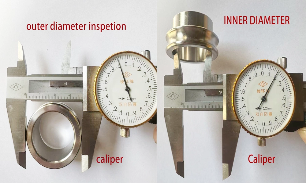
Suitable for general dimensional checks, typically with an accuracy of ±0.05 mm.could check OD (outer diameter) and ID( inner diameter ) by vernier caliper same time .
Dial & Digital calipers introduction
Higher precision, suitable for general dimensional checks, typically with an accuracy of ±0.02 mm.
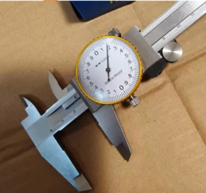
Digital calipers are commonly used in brass and aluminum CNC parts factories because they are easy to read for low education workers.However, they are not ideal for iron or stainless steel workshops. During CNC machining, workers hand keep have oil and cutting fluid so dial caliper will be better choice . Digital caliper will directly destroy by the cutting fluid and affect the digital caliper service life . And digital caliper costs higher than dial caliper , during inspecion time , Digital calipers often experience changes in size, or changes in the numbers, which can lead to measurement accidents, so they need to be calibrated more frequently.
Basic operation
-
Micrometers
Used for high-precision external measurements, with typical accuracy of ±0.01 mm.
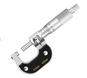
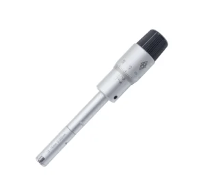
Micrometers for outdiameter Three-jaw micrometer for inner diameter
-
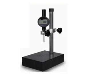
Height gauges
Ideal for measuring vertical distances or heights relative to a reference surface, with accuracy around ±0.02mm.
Go/No-Go gauges (plug gauges / ring gauges) – Functional inspection tools that confirm whether parts meet specific limits, but do not provide detailed dimensional data.
A Go/No-Go gauge is a type of inspection tool used to quickly check whether a part’s dimensions are within tolerance. It is commonly applied in CNC machining, metalworking, and precision manufacturing in China and worldwide.
-
Go side: ensures the part is at least within the minimum required dimension; the gauge should fit or pass through smoothly.
-
No-Go side: ensures the part does not exceed the maximum allowed dimension; the gauge should not fit or pass through.
Principle
The Go/No-Go gauge works on a simple principle:
-
The Go end corresponds to the lower or upper tolerance limit, guaranteeing the part meets minimum requirements.
-
The No-Go end corresponds to the opposite tolerance limit, preventing oversized or undersized parts.
-
If the Go end passes and the No-Go end does not, the part is considered within specification.
Usage
-
Holes: Go gauge should fit inside the hole; No-Go gauge should not.
-
Shafts: Go gauge should slide over the shaft; No-Go gauge should not.
-
Threads: Go thread plug gauge or ring gauge should rotate smoothly; No-Go gauge should not rotate beyond the allowed number of turns.
Key Features
-
Fast and intuitive: ideal for production line inspection.
-
No measurement reading required: directly indicates pass/fail.
-
High repeatability: simple design, easy to operate.
-
Limitation: cannot provide exact deviation, only indicates compliance.
Practical Limitations of Plug Gauges in Hole Inspection
- In real manufacturing applications, plug gauges (Go gauges) are widely used as fast inspection tools for hole size verification. However, practical experience shows that plug gauge results do not always perfectly match micrometer or CMM measurements. For example, when a drawing specifies an internal control tolerance of 10.05–10.08 mm, and a plug gauge is manufactured exactly at 10.05 mm, issues may occur during inspection. Even if a three-point bore micrometer measures the hole diameter at 10.05 mm, the plug gauge may still fail to enter the hole.
- Based on repeated testing in CNC machining factories in China, this discrepancy is mainly caused by measurement method differences and surface conditions. In practice, an average deviation of approximately 0.015 mm has been observed. To achieve functional consistency, a 10.035 mm plug gauge is often required to smoothly enter a 10.05 mm internal hole. This deviation highlights that plug gauges evaluate functional fit, while micrometers measure local diameter values, which may not fully represent the entire hole condition.
- In addition, hole surface finish plays a significant role in plug gauge inspection. Surface roughness, tool marks, or slight taper can increase insertion resistance, causing plug gauges to indicate nonconformance even when dimensional measurements appear acceptable. For this reason, professional CNC machining and inspection processes consider plug gauge tolerance, surface finish, and inspection purpose together, rather than relying on nominal size alone, to ensure reliable and consistent quality control for global customers.
- Summary
A Go/No-Go gauge uses two standard limits (Go and No-Go) to quickly determine whether a part is within tolerance. It is widely used for shafts, holes, threads, and other precision components in CNC machining and manufacturing factories in China and globally.
-
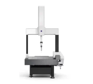
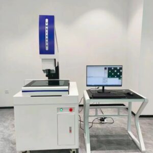
Coordinate Measuring Machines (CMM)
Highly precise, computer-controlled inspection, with accuracy up to ±0.002–0.005 mm, suitable for complex geometries.
-
Features of Coordinate Measuring Machines (CMM)
-
High Precision 3D Measurement – Can measure complex geometries in three dimensions with very high accuracy (typically ±0.002–0.005 mm).
-
Versatile Measurement – Suitable for lengths, diameters, angles, positions, flatness, perpendicularity, concentricity, and other geometric tolerances.
-
Automation and Repeatability – Computer-controlled probe movement ensures consistent, repeatable measurements.
-
Non-destructive Inspection – Can measure delicate or finished CNC parts without damaging surfaces.
-
Supports Complex Shapes – Especially useful for parts with intricate features that are difficult to measure with calipers or micrometers.
-
Software Integration – Can generate reports, compare to CAD models, and perform statistical analysis for quality control.
-
Environmental Sensitivity – Accuracy can be affected by temperature, vibration, and probe calibration, so a controlled environment is required.
-
-
Basic Process
- Obtain Drawings / 3D Model
Engineers provide the part’s 2D technical drawing or 3D CAD model.
The 3D CAD model contains all dimensions, tolerances, hole positions, surfaces, and other relevant information. - Create Measurement Program in CMM Software
Based on the drawing or CAD model, measurement personnel define key measurement points, scanning paths, and tolerance requirements.
Modern CMM software can directly import the CAD model to generate the measurement program, including points, contours, and surfaces. - Measurement
The probe follows the program to contact or scan the part surface.
The machine records the X/Y/Z coordinates using linear encoders and calculates dimensions such as length, hole diameter, position, flatness, roundness, etc. - Generate Inspection Report
The software compares the measured values with the drawing specifications and outputs a report indicating pass/fail status and deviations.
Supplementary Notes
-
For simple dimension parts (such as standard outer or inner diameters), measurements can be performed manually or with quick CMM point checks, without requiring a full 3D model.
-
For complex surfaces or precision components (such as aerospace parts or automotive molds), a 3D CAD model is generally required, and the CMM may scan surfaces or capture point clouds for comparison.
-
In some cases, parts are produced first and then scanned with the CMM to generate a reverse 3D model for inspection or reverse engineering. This process is called reverse measurement.
-
Optical / Vision Measurement Systems
We also called profile projector ,Non-contact methods, typically accurate to ±0.003–0.01 mm, useful for delicate
surfaces or thin-walled CNC parts.
Features of Optical Projectors (Optical Comparators)
-
Non-contact Measurement – Measures dimensions without physically touching the CNC part, preventing surface damage.
-
Magnified Profile Viewing – Projects an enlarged shadow or image of the part onto a screen, making it easier to detect small deviations.
-
High Precision for 2D Profiles – Ideal for measuring cross-sections, contours, holes, and threads with reasonable tolerances.
-
Quick Inspection – Allows rapid measurement of multiple parts in batch production.
-
Versatile Measurement – Can measure angles, diameters, distances, and compare the part to templates or CAD drawings.
-
Sensitive to Surface Finish & Lighting – Reflective or dark surfaces may require coating or proper lighting adjustment.
| Measurement Tool | Typical Accuracy | Best Use Case | Limitation |
|---|---|---|---|
| Vernier Caliper (non-dial) | ±0.05 mm | General dimensional checks | Human error, contact pressure affects result |
| Dial & Digital Caliper | ±0.02 mm | General dimensional checks | Requires calibration, still contact-based |
| Micrometer | ±0.01 mm | High-precision external diameters | Cannot measure internal features easily |
| Height Gauge | ±0.02 mm | Vertical dimensions, step heights | Requires stable reference surface |
| Plug / Ring Gauge | Pass/Fail | Functional acceptance, tolerance check | No detailed dimensional data |
| CMM | ±0.002–0.005 mm | Complex geometries, full 3D inspection | High cost, programming & environment sensitive |
| Optical / Vision System | ±0.003–0.01 mm | Non-contact, delicate or reflective surfaces | Surface finish can affect accuracy |
Contact vs. Non-Contact Inspection: Which Is More Accurate?
In manufacturing and quality control, there is no absolute answer as to whether contact or non-contact inspection is more accurate. Accuracy largely depends on the application, material properties, and surface condition of the part. Contact inspection methods, such as CMM touch probes, calipers, and micrometers, obtain dimensional data through physical contact with the part surface. These methods offer high stability and repeatability and are widely used for metal components with tight tolerances. However, for thin-walled parts, soft materials, or components with surface treatments, physical contact may cause slight deformation or damage to the coating, such as anodized or electroplated layers, which can affect measurement results.
Non-contact inspection methods, including optical measurement systems, vision inspection, and laser scanning, measure parts without physical contact, making them suitable for delicate parts, thin-wall structures, and precision components. However, non-contact inspection is highly sensitive to surface color, reflectivity, and coating condition. In practical applications, highly reflective electroplated parts, dark black oxide components, or uneven anodized surfaces may lead to unstable readings unless surface treatment or parameter adjustments are applied.
In CNC machining and surface treatment factories in China, contact and non-contact inspection methods are often used in combination. For example, anodized aluminum parts are commonly verified with contact CMM inspection for critical dimensions, while non-contact optical inspection is applied to complex geometries or thin-walled features. This hybrid approach ensures reliable dimensional accuracy and consistent quality control in accordance with international manufacturing standards.
Operator Skill and Measurement Consistency
In dimensional inspection, operator skill plays a critical role in measurement consistency, even when the same part and the same measuring tool are used. In real manufacturing environments, especially in CNC machining factories, different operators may obtain different measurement results due to variations in measuring force, measurement point selection, and measurement repetition methods. Excessive measuring force can deform thin-walled parts, while inconsistent measurement positions can lead to unstable or non-repeatable results.
It is normal to get the customer complain that size is not approved , but when we check innter department , result is aprroved . So the same methods to test cnc parts is a important things before cnc machining.
To reduce human-related variation, professional factories establish standard operating procedures (SOPs) for inspection. An SOP clearly defines how to measure, where to measure, how many times to measure, and how to record the final value (for example, using average values or maximum deviation). Without a unified SOP, measurement results depend heavily on individual experience rather than a controlled process.
In addition, advanced manufacturers perform Measurement System Analysis (MSA) to evaluate whether the measurement process itself is reliable. A key part of MSA is GR&R (Gauge Repeatability and Reproducibility), which analyzes how much variation comes from the measuring instrument and how much comes from different operators. If GR&R results are unacceptable, it indicates that measurement inconsistency—not part quality—may be the root cause of inspection variation. For this reason, MSA and GR&R are widely used in precision CNC machining and quality control systems to ensure reliable and consistent inspection results for global customers.
Environmental Factors in Precision Measurement
In high-precision measurement, environmental conditions have a direct impact on measurement accuracy, yet this is often overlooked by non-technical customers. Even when the same part and the same measuring equipment are used, changes in temperature, humidity, and inspection location can lead to different results.
Temperature variation is one of the most critical factors. Metal parts expand or contract with temperature changes, especially aluminum and steel components commonly used in CNC machining factories . If a part is measured immediately after machining, it may still be warm, resulting in inaccurate dimensions. Allowing sufficient cooling and stabilization time before inspection is essential for reliable results.
Humidity also affects precision measurement, particularly in optical or non-contact inspection systems. High humidity can influence sensor performance and surface reflectivity, leading to unstable readings. In addition, measurements taken in a controlled inspection room are typically more stable and repeatable than those taken directly on the shop floor, where temperature and airflow vary.
Surface treatment further increases measurement complexity. Dimensions measured before and after anodizing, electroplating, or black oxide treatment may differ due to coating thickness and surface changes. For this reason, professional manufacturers clearly define inspection conditions and environments to ensure consistent and trustworthy measurement results for global customers.
How to Choose the Right Inspection Method Based on Tolerance Requirements
Selecting the appropriate inspection method should be driven by tolerance requirements, not by habit or equipment availability. For parts with loose or general tolerances, such as standard fittings,hose fitting, pipe connector or non-critical features, basic tools like calipers, micrometers, or Go/No-Go gauges are often sufficient. These methods are fast, cost-effective, and well suited for high-volume production where pass/fail decisions are required. Also for satisfy more customer , we also purchased profile projector could satisfy radius, angle , thread angle etc.
When parts require tight dimensional tolerances or geometric control, especially for position, coaxiality, perpendicularity, or runout, CMM (Coordinate Measuring Machine) inspection becomes essential. CMMs provide stable, repeatable measurements and allow features to be evaluated relative to defined datums, making them ideal for precision CNC machining. For simple holes or shafts with strict limits, plug gauges or ring gauges may still be more efficient than a full CMM program, offering a good balance between speed and accuracy. But CMM test machine is one big cost machine , the mostly factories is no have power to keep this inspection machine .
In practice, professional CNC machining factories select inspection methods based on a balance between cost and precision. Over-inspection increases cost without adding value, while under-inspection risks quality issues. Choosing the right inspection strategy ensures reliable quality control while keeping manufacturing costs competitive for global customers.
Conclusion: Product Accuracy Is Determined by Both Machining and Inspection
Product accuracy is not defined by machining alone. It is the result of both machining capability and inspection capability working together. Even the most precise CNC machine cannot guarantee product quality without a reliable and consistent inspection process to verify the results.
Inspection is not a secondary or optional step—it is a core part of the quality management system. Differences in inspection methods, measurement environments, and quality control standards often explain why products with similar drawings can have different prices. In China’s CNC manufacturing industry, factories that invest in both advanced machining and professional inspection systems are able to deliver stable quality, reduce disputes, and meet international customer expectations.
Understanding that machining accuracy + inspection accuracy = true product quality helps customers make informed decisions when evaluating suppliers, pricing, and long-term manufacturing partnerships.